Enterprise-Grade SD-WAN: SteelConnect EX Advanced Routing Capabilities
- By Riverbed Technology
- 27-Apr-2020
Advanced network routing is one of the most powerful features of Riverbed’s enterprise-grade SD-WAN solution SteelConnect EX – definitely one of my favorites. While other vendors took a different path offering the minimum feature set, SteelConnect EX implements all the advanced routing capabilities Enterprise Network Architects need to get full control of their infrastructure, at scale.
In previous posts, I gave an architecture overview of SteelConnect EX as well as provided general principles to integrate SteelConnect EX in a data center. In this blog, I will provide a deep dive into the routing and SD-WAN mechanisms of SteelConnect EX. I will not detail how to configure static routing, BGP, or OSPF, but will focus on the internal mechanisms of Riverbed’s SD-WAN solution.
So buckle up and let’s proceed.
Virtual Routers
When you consider a SteelConnect EX branch appliance, it’s not simply an SD-WAN router; it’s a system that runs multiple virtual routers (VR). Why multiple routers? That’s what we are going to address right now. Trust me, it makes our solution one of the most elegant and powerful SD-WAN solution for attaining maximum control.
So what is a virtual router in the first place?
By virtual router, I don’t mean a virtual appliance that you would deploy on a hypervisor. The architecture we are going to review is the same on any type of SteelConnect EX appliance: hardware, virtual and cloud images.
Virtual routing instances allow administrators to divide a device into multiple independent virtual routers, each with its routing table. Splitting a device into many virtual routing instances isolates traffic traveling across the network without requiring multiple devices to segment the network.
Virtual routing and forwarding (VRF) is often used in conjunction with Layer 3 sub-interfaces, allowing traffic on a single physical interface to be differentiated and associated with multiple virtual routers. Each logical Layer 3 sub-interface can belong to only one routing instance.
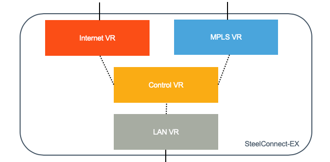
Besides the global routing instance, which is the main one and used for management, there are three types of instances:
- Transport VR: each circuit has a separate VR with its routing table and routing protocols. You can create a Transport VR for MPLS, one for Internet, another one for 4G/LTE. The Transport VR is part of the underlay network; it interacts with the rest of the network and it owns a network interface (or sub-interface if you use VLANs). The system allows up to 16 uplinks.
- The Control VR is tied to an organization (tenant). It has no physical interface attached to it. It is the entry point to the SD-WAN overlay. It forms tunnels with remote sites and with the Controller. It forwards “user” traffic through the overlay to other SD-WAN equipped sites. Several LAN VRF can be attached to one Control VR.
- The LAN VRF is also tied to an organization because it is paired with a Control VR (and only one). Multiple LAN VRF can be created to segment the traffic.
What is the benefit of having three types of instances? Let’s have a look at how we are using those VRs for SD-WAN.
Roles of the Routing Instances for SD-WAN
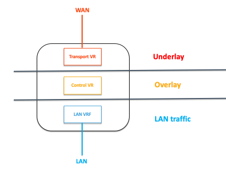
A simple way to summarize the role of each instance would be the following:
- Transport VR is the underlay
- Control VR is the overlay
- LAN VRF is the LAN traffic
Let’s consider connecting to a server hosted in another site across the WAN. This site is also equipped with a SteelConnect EX gateway.
Our workstation will send traffic to its default gateway and will eventually hit the LAN VRF. The first thing that the appliance will do is a route lookup. Since the other site is also part of the SD-WAN overlay, the Control VR will advertise the server subnet to the LAN VR. Thus the packets will be routed to the Control VR, which is going to encapsulate in the overlay tunnel.
The tunnel is going over the Transport circuits. Depending on the SD-WAN policies, the uplinks will be bonded (by default) or App-SLA based path selection rules will kick in and steer the traffic in a particular uplink.
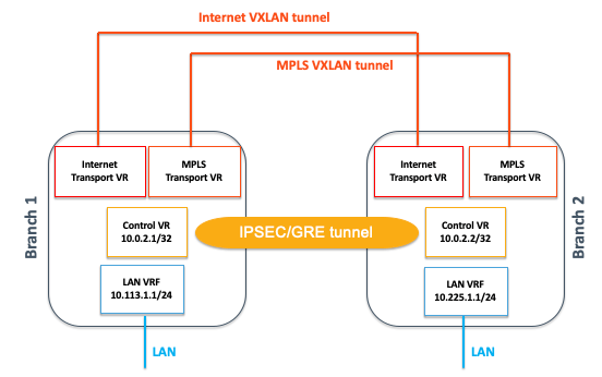
The overlay is a tunnel built on several layers of encapsulation:
- On top of each transport domain (Internet, 4G/LTE, MPLS, etc.), a stateless VXLAN tunnel will be created between gateways.
- Between Control VRs of two gateways are formed one (and only one) stateful IPSEC (over GRE) tunnel, which is transported on the VXLAN tunnels formed on the underlay (remember the Control VR has no physical interfaces).
Wait! Why do we have so many encapsulation happening? What is the impact on performance? I know these questions popped up in your head as you were reading the previous section.
Overlay Efficiency
Let’s rewind a bit and discuss the VXLAN piece first. Within a transport domain–by default and unless specified otherwise like creating Hub&Spoke topologies–all gateways will automatically form VXLAN between each other. As a result, two sites with an MPLS-A uplink will have a VXLAN tunnel between each other. If one site is Internet-only and the other MPLS-only, they won’t form tunnels; the only way for those two sites to communicate with each other will be to go to a hub connected to both transport domains.
VXLAN is a well-known technology in data centers that build Layer 2 networks on top of Layer 3. It uses flow-based forwarding and is known as being more efficient than a traditional Layer 3 routing that routes packets separately. Furthermore, VXLAN can scale much better than other tunneling technologies like IPSEC with an address space that can go over 16M entries.
On top of VXLAN, various IP transport tunnels can be implemented. In the case of SteelConnect EX, the Control VR will build IPsec over GRE for untrusted networks (by default) or simply GRE for the trusted ones.
Other SD-WAN solutions on the market form IPSEC tunnels on each uplink–most of them are always-on and rarely on-demand, otherwise performance is penalized during switchovers. In a full-mesh network, the complexity is O(n^2), in fact, O(n^2 x L^2) where n is the number of sites and L the number of uplinks, which becomes very quickly resource angry on a system.
Since Control VRs are creating only one IPSEC tunnel with remote sites, no matter how many uplinks there are, we have a much more efficient system that can very quickly failover in case of a WAN outage whilst consuming less resources.
All the encapsulation happens in the Control VR.
As you can see, an MPLS (VPN) label is attached to each LAN VRF. MPLS? Yes! We are leveraging MPLS technologies, too: Control VRs are forming a Virtual MPLS Core network.
In total, the overhead is 58 bytes for encrypted traffic hence the MTU would be 1342 bytes by default.
To be exact, enabling each path resiliency feature (like FEC, packet replication or packet stripping) would add 12 bytes of overhead each.
Split Tunnels
Now that we have a better understanding of the system architecture and the overlay mechanism, let’s have a look at the routing between VRs. Split tunnels refer to the menu that will be used to pre-configure the inter-VRs routing using Workflows on the Director.
When I teach a class on SteelConnect EX, I usually ask engineers in the room what they would need to do to have a packet routed between LAN and WAN with the following diagram:
The first thing we need to do is interconnect the routers with a cable. We also need to set an IP address on each of the routers’ interfaces. Finally, we need some sort of routing: static routes or a dynamic protocol like BGP.
It may sound obvious, but bear with me, this approach is super helpful to picture how the system works. On SteelConnect EX, the creation of all of those items is automatic and the configuration is pushed from the Director:
- IP addresses will be automatically set on the VRs for internal use (LAN and WAN interfaces will need to be configured though)
- The “virtual wire” is a tunnel to interconnect the routers that the system builds for us
- BGP peering is configured to exchange routes
By default, a tunnel is created between the LAN VRF and the Control VR. BGP peering is established on the routing instances. The LAN-VRF advertises its direct connected subnets to the Control VR so they are visible on the SD-WAN overlay. The Control VR advertises all subnets from the SD-WAN fabric to the LAN-VRF. When you leave the split tunnel configuration empty, this is what happens.
“Passthrough”
During the template creation using Workflows, when the split tunnel is configured between the LAN-VRF and the Transport VR (say MPLS) with no options ticked, this is what we call the passthrough mode.
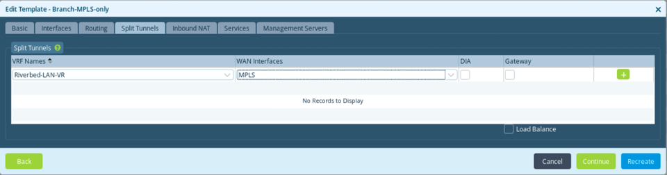
What happens when we implement that?
A tunnel is created between the LAN VRF and the Transport VR (here MPLS) to directly interconnect them. BGP peering is established between the two routing instances, which allows the LAN VRF to be aware of underlay subnets as well as the LAN VRF subnets to be advertised on the MPLS network. This is helpful in a hybrid deployment where SD-WAN and traditional routers will coexist.
DIA: Direct Internet Access
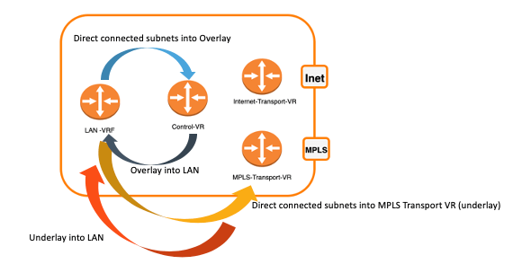
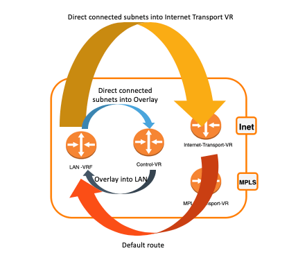
Again, leveraging the power of automation, when we select the option DIA in the split tunnel configuration, many things happen in the background to achieve your goal, which is to put in place direct Internet breakout.
In addition to the routes exchanged between the LAN VRF and the Control VR, a tunnel is created between the LAN VRF and the Transport VR (here Internet) to directly interconnect them. BGP peering is established between the two routing instances, which allows the LAN VRF to advertise its direct connected subnets to the Internet Transport VR. The latter will advertise a default route to the LAN VRF. Finally, CG-NAT is configured for all outbound traffic on the Internet.
Gateway
Finally, the last option is to select “Gateway.”
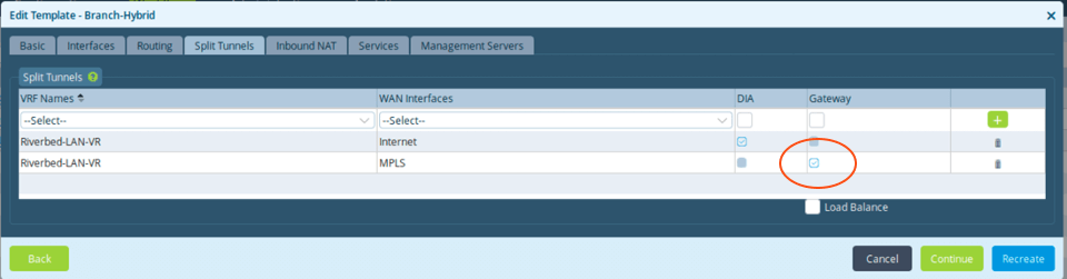
In this case, the subnets from the overlay will leak into the underlay (here MPLS) and vice-versa; subnets learned from the underlay will be advertised into the SD-WAN.
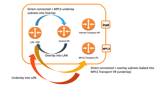
This feature allows you to implement transit use cases between the SD-WAN fabric and underlay networks, as well as disjoint networks.
Conclusion
Today, we have learned that SteelConnect EX grants full control and flexibility to build the SD-WAN fabric on top of the traditional network.
There are three types of routing instances with different roles:
- Transport VR is the underlay
- Control VR is the overlay
- LAN VRF is the LAN traffic
What we did not cover here is the multi-tenancy capability of the solution and this will be addressed in the next blog.
A question, a remark, some concerns? Please don’t hesitate to engage us directly on Riverbed Community.