Onboarding SteelConnect EX Branches with a Staging Script
- By Riverbed Technology
- 29-Apr-2020
[embedyt] https://www.youtube.com/watch?v=9zGajxUImvM[/embedyt]
After you’ve deployed a SteelConnect EX SD-WAN headend, common next steps are to onboard branches to the headend, place them into the SD-WAN fabric, and allow them to be managed via overlay by the Director. In this article, we are going to walk through the process of using a staging script to onboard an Internet-only SD-WAN site. To do this, we have to complete a bit of pre-work first. We need to update the topology to add Branch D (I’m using the same environment that I used in the above-referenced article and video), configure some templates, and then use the script to onboard the device. To begin, let’s have a look at the topology. I’m using GNS3 because it makes it simple to add and delete sites, links, etc.
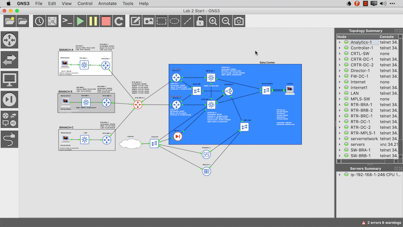
In the above topology you can see that the headend is already deployed and that I have three sites that are MPLS only. We will migrate those in other articles but in this one, we are going to add a brand new branch called Branch D and connect it to the Internet cloud. You can see this in the image below.
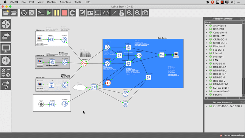
Now that the topology is ready, I want to start the VM so that it’s ready when I get to the point of onboarding it. In the meantime, I need to provision things in the Director interface. Let’s start there.
Creating a workflow template for branch onboarding
When you onboard a branch you do so using a template. There are several types of templates available to you in the SteelConnect EX SD-WAN solution, however what we want to start with is a Workflow Template.
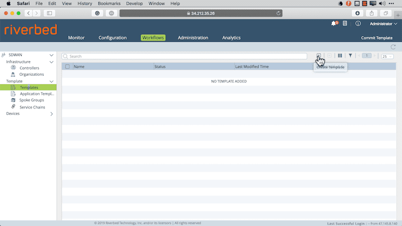
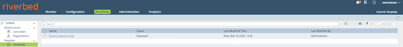
- First, navigate to Workflows>Templates>Templates
- Then click the + button to add a template.
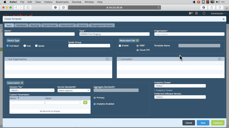
We need to populate a few values here. These include providing a name, selecting the type of template we are using, the organization, controllers, subscription information, and analytics cluster. Some of these values are required to move on. You’ll note that this is a multi-tabbed template so we have a few pages that will require us to provide configuration data. You can see the first page below.
After clicking continue, you now provide the Interfaces configuration. Take note of how the device is physically wired and also that there are no device-specific values here. This is a template after all. Multiple devices can be deployed using this template. Below is what my interface configuration looks like for this deployment.
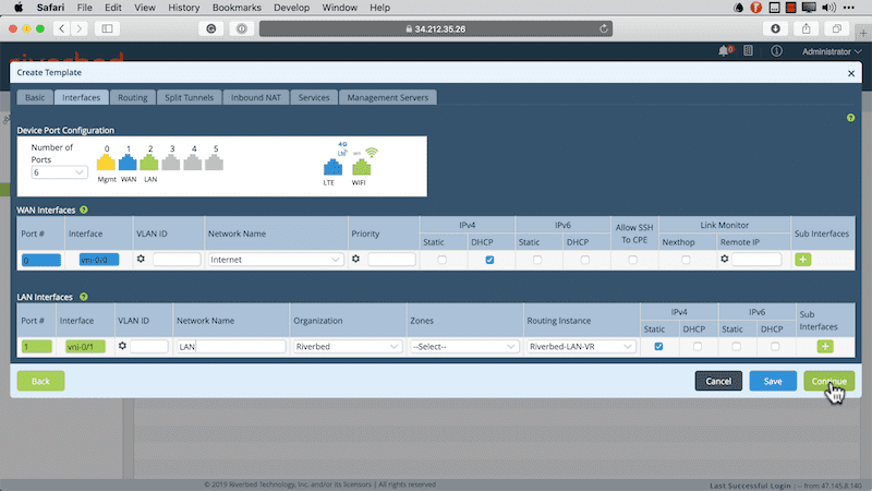
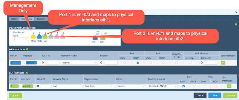
One thing to note here is that the interfaces I’m using are port 1 and 2. This is because port 0 is reserved for management. Therefore, port 1 is mapped to vni-0/0 (which is the WAN interface) and port 2 is mapped to vni-0/1 (which is our LAN side interface).
The next tab is the Split Tunnels page, where you map your VRF to a WAN VR and define that we will use DIA (Direct Internet Access) for devices onboarded with this template. DIA ensures that Internet-bound traffic is sent directly to the underlay and not backhauled to the data center. There’s actually a lot that goes on behind the scenes here. Not only is NAT configured, but BGP connectivity is established between the WAN VR and the LAN VRF so that routing between the two can take place.
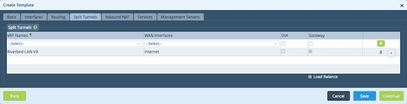
Be sure to click the + button or the DIA will not be applied.
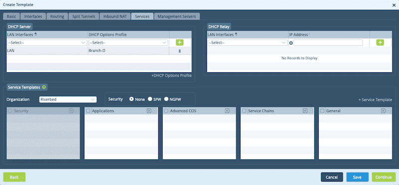
On the next page, we need to configure our DHCP values for the LAN side. This will allow onboarded branches to allocate DHCP addressing to devices in that branch.
On the last page, you can click the Create button and your template will be committed to the Director. Once this is done, it’s time to add a device. Before adding the device, ensure that the template was committed successfully. You can check this by clicking the refresh icon to see if the template shows up in the list.
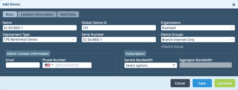
Next, we add the device and attach it to a device group. The device group has the template defined that was created earlier. You can add the Device Group as part of the Add Device workflow. We do this Under Workflows, by clicking on Devices and then the + symbol.
In the form fields, you need to provide all the required values. This includes providing a name, selecting an organization, providing a serial number that you create (I use the device name here for simplicity), and then clicking the +Device Group Link.
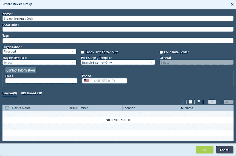
When the Create Device Group page appears we can provide a name, select the organization, select the template you previously created as the Post Staging Template and then click OK. You can see this in the image below.
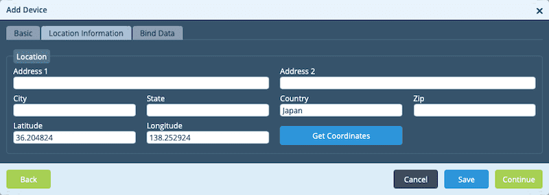
We then proceed to the Location Information page. On this page, the only mandatory field is the Country field. However, make sure you click the Get Coordinates button and that the latitude and longitude populate or you will need to manually enter these as well.
The next page we need to work with is the Bind Data Page. This is where we tie the variables in the template to the actual device.
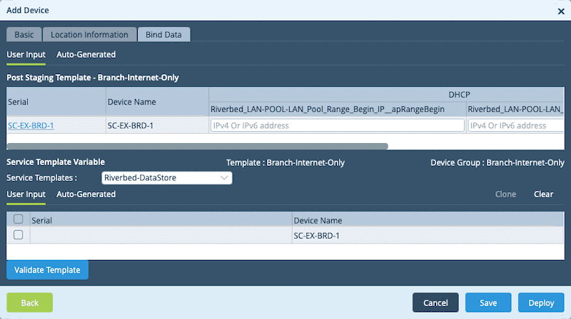
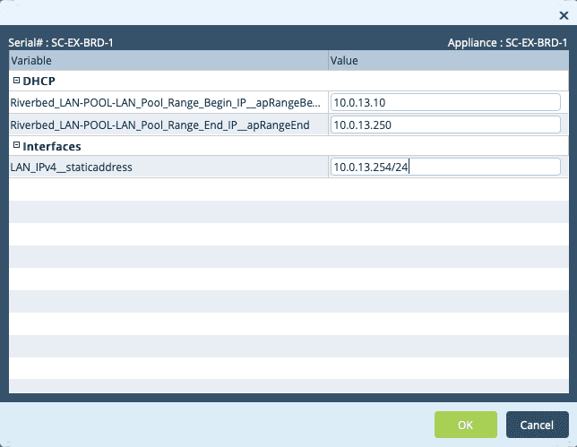
We can click on the Serial Number link to see the variables on one page. From here, we can enter the required values and then deploy the device.
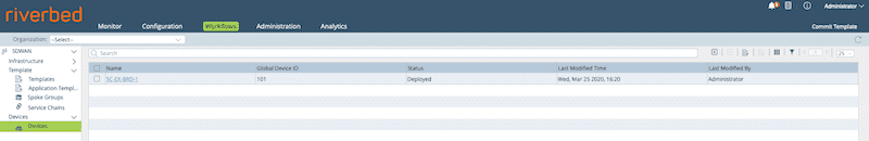
As we did with the template, we should verify that it shows up in the device list now.
Now comes the part we’ve all been waiting for: staging the device using ZTP. We do this from the CLI of the SteelConnect EX that we put in our topology at the onset of this article.
Stage the device using ZTP
Once on the CLI of the SteelConnect EX appliance, we need to navigate to the scripts directory.
cd /opt/versa/scripts/
Once there we run the deployment script. Here is an example of the staging script that I ran in the topology I’m working in. Essentially we set the local and remote IKE identities, define the serial number, set the controller IP address and then use DHCP on Wan 0. Now, a few things to clear up here. First, the controller IP is a “Public” address. In my lab that’s the “192.168.122.x” address space. Because this is an Internet-only branch, I need to onboard through the firewall at the edge of the data center. I’ve already configured static NAT and access rules on the firewall to allow this to happen. The second thing to clear up is that I said to use Wan 0 in the script, but I’m really plugged into eth1. That’s because eth0 is dedicated to management so the first physical port is port 0 according to the SteelConnect EX software. This maps to vni-0/0.
sudo ./staging.py –l SDWAN-Branch@Riverbed.com –r Controller-1-staging@Riverbed.com -n SC-EX-BRD-1 –c 192.168.122.25 –d –w 0
Once the command is executed, the FlexVNF instance will initiate an IPSec connection to the controller. You will also see the following output on the command line.
=> Setting up staging config
=> Checking if all required services are up
=> Checking if there is any existing config
=> Generating staging config
=> Config file saved staging.cfg
=> Saving serial number
=> Loading generated config into CDB
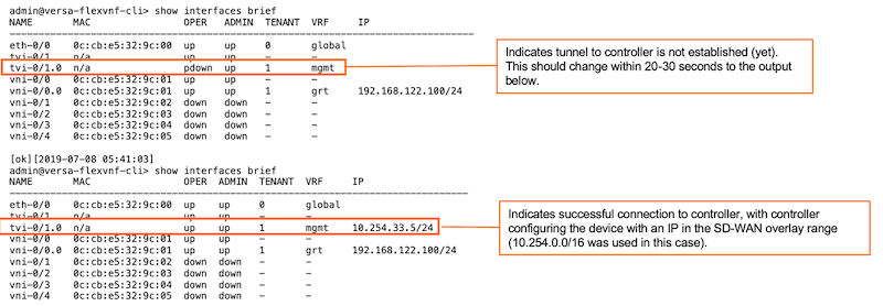
After you run the script, things sort of happen in the background. We can go to the CLI of the SteelConnect EX and use the show interfaces brief command to confirm:
[admin@versa-flexvnf: scripts] $ cli

admin connected from 127.0.0.1 using console on versa-flexvnf
admin@versa-flexvnf-cli> show interfaces brief | tab
NAME       MAC                OPER  ADMIN  TENANT  VRF     IP
-------------------------------------------------------------------------------
eth-0/0    0c:cb:e5:f9:c1:00  up    up     0       global
tvi-0/1    n/a                up    up     -       -
tvi-0/1.0  n/a                up    up     1       mgmt    10.254.33.3/24
vni-0/0    0c:cb:e5:f9:c1:01  up    up     -       -
vni-0/0.0  0c:cb:e5:f9:c1:01  up    up     1       grt     192.168.122.157/24
vni-0/1    0c:cb:e5:f9:c1:02  down  down   -       -
vni-0/2    0c:cb:e5:f9:c1:03  down  down   -       -
vni-0/3    0c:cb:e5:f9:c1:04  down  down   -       -
vni-0/4    0c:cb:e5:f9:c1:05  down  down   -       -
What happens next is expected. During the process of checking the tunnel, the device is being provisioned so we see messages that a commit was performed via ssh using netconf. This is the Director provisioning the device with the values we defined when we deployed the device in the Director GUI. Once provisioned, the device will reboot. You should see the following:
admin@versa-flexvnf-cli>
System message at 2019-08-04 22:24:34...
Commit performed by admin via ssh using netconf.
admin@versa-flexvnf-cli>
System message at 2019-08-04 22:24:40...
Commit performed by admin via ssh using netconf.
admin@versa-flexvnf-cli>
Broadcast message from root@versa-flexvnf
        (unknown) at 22:24 ...

The system is going down for reboot NOW!

System message at 2019-08-04 22:24:50...
    Subsystem stopped: eventd

System message at 2019-08-04 22:24:50...
    Subsystem stopped: acctmgrd
admin@versa-flexvnf-cli> admin@versa-flexvnf-cli>
System message at 2019-08-04 22:24:50...
    Subsystem stopped: versa-vmod
admin@versa-flexvnf-cli>
versa-flexvnf login:
Digging a bit deeper into the provisioning output, note the following:
Once successfully connected, the FlexVNF appliance will automatically go for a reboot and load the correct config. If that’s the case, you can skip the next step.
After the reboot of the FlexVNF appliance, you should see the different virtual routers:
We need to go back into the CLI of the SteelConnect EX at Branch D and issue the command to view the interfaces.
admin@SC-EX-BRD-1-cli> show interfaces brief | tab
NAME          MAC                OPER   ADMIN  TENANT  VRF                    IP
--------------------------------------------------------------------------------------------------
eth-0/0       0c:cb:e5:32:9c:00  up     up     0       global
ptvi1         n/a                up     up     2       Riverbed-Control-VR    10.254.24.1/32
tvi-0/2       n/a                up     up     -       -
tvi-0/2.0     n/a                up     up     2       Riverbed-Control-VR    10.254.17.44/32
tvi-0/2602    n/a                up     up     -       -
tvi-0/2602.0  n/a                up     up     2       Internet-Transport-VR  169.254.7.210/31
tvi-0/2603    n/a                up     up     -       -
tvi-0/2603.0  n/a                up     up     2       global                 169.254.7.211/31
tvi-0/3       n/a                up     up     -       -
tvi-0/3.0     n/a                up     up     2       Riverbed-Control-VR    10.254.25.44/32
vni-0/0       0c:cb:e5:32:9c:01  up     up     -       -
vni-0/0.0     0c:cb:e5:32:9c:01  up     up     2       Internet-Transport-VR  192.168.122.149/24
vni-0/1       0c:cb:e5:32:9c:02  up     up     -       -
vni-0/1.0     0c:cb:e5:32:9c:02  up     up     2       Riverbed-LAN-VR        10.0.13.254/24
vni-0/2       0c:cb:e5:32:9c:03  down   down   -       -
vni-0/3       0c:cb:e5:32:9c:04  down   down   -       -
vni-0/4       0c:cb:e5:32:9c:05  down   down   -       -
We should also verify that we can reach addresses on the Internet from the CLI:
admin@SC-EX-BRD-1-cli> ping 1.1.1.1 routing-instance Internet-Transport-VR
Bind /etc/netns/Internet-Transport-VR/resolv.conf.augsave -> /etc/resolv.conf.augsave failed: No such file or directory
PING 1.1.1.1 (1.1.1.1) 56(84) bytes of data.
64 bytes from 1.1.1.1: icmp_seq=1 ttl=50 time=5.35 ms
64 bytes from 1.1.1.1: icmp_seq=2 ttl=50 time=2.23 ms
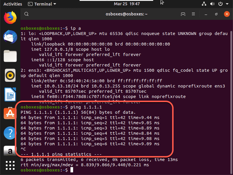
And finally from the Ubuntu client that we placed in the branch we want to see if it received a DHCP address.
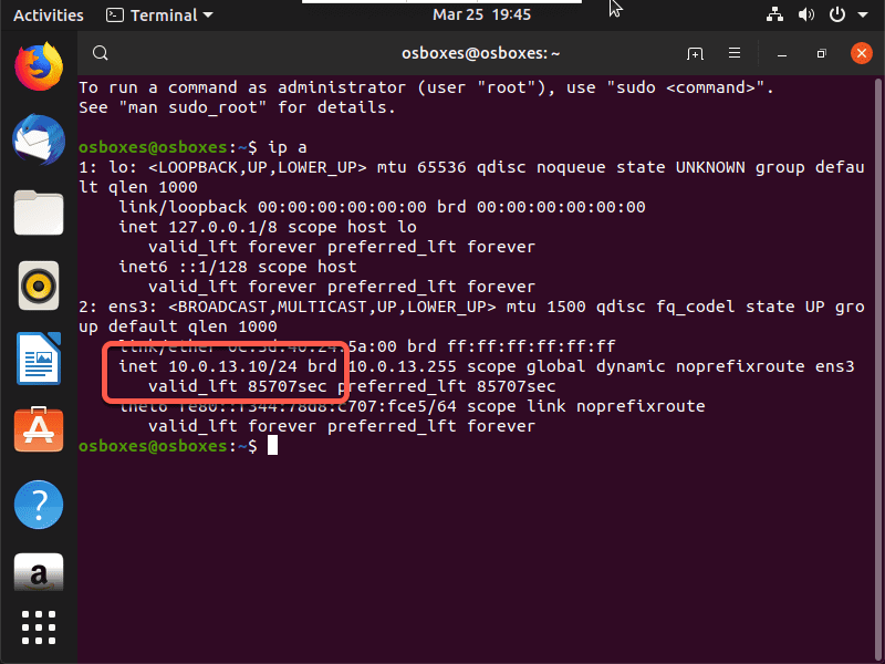
Since we have an IP address, we should try to ping and when we do we can see that DIA is working as expected.
Wrap up
Well, this is just one example of how to onboard branches in the SteelConnect EX SD-WAN solution. There’s also the URL-ZTP method, but we can save that for another article. Either way you choose the result should be the same. The device will become part of the SD-WAN fabric, establish an overlay to the controller, and then overlays between other sites once others are onboarded as well.